Cryogenic liquid microjet generation
A liquid expanding through a pinhole orifice (a "nozzle") into a high vacuum region delivers a uniquely functional target in the form
of a droplet beam. The main features of the droplet beam strongly depends on the source parameters, specifically source pressure and source temperature,
as shown in Fig. 1. In general, one observes on cooling, and for a fixed pressure, a continuous transition between the cavitation-induced fragmentation
and the Rayleigh breakup of the liquid stream (Grisenti and Toennies, 2003). In the
former case an disruptive explosion of the liquid occurs, delivering broad distributions of droplet sizes and directions
(i.e., a "spray" is produced), whereas the latter case corresponds to the laminar flow regime, in
which the continuous cylindrical liquid filament spontaneously breaks up as a result of Rayleigh-induced oscillations into a monodirectional and nearly
monodisperse stream of droplets, also termed Rayleigh droplet beam (RDB). Owing to their boundary-free, self-replenishing nature, liquid droplet beams
have found widespread applications, ranging from practical contexts such as microfluidics, cop- and paint-spraying, and ink-jet printing, to more
fundamental research studies such as soft x-ray generation, photoelectron spectroscopy, and femtosecond x-ray crystallography. In our group at the
Institut für Kernphysik (IKF) we develop cryogenically cooled microscopic liquid jets into unique and powerful tools for novel applications in
atomic, plasma, and
condensed matter physics.
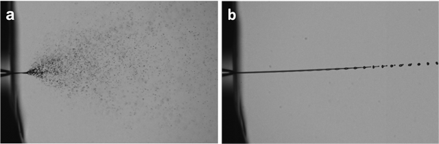
- Figure 1. Nitrogen droplet
beams produced from a 5 μm diameter glass capillary in a vacuum chamber especially dedicated for these activities at IKF and characterized by means of
shadow-imaging techniques. The beam in (a) was produced at a source pressure of 10 bar and at a source temperature of 88 K, clearly showing the
cavitation-induced disruptive fragmentation of the expanding liquid filament. The beam in (b) was produced at 10 bar and 80 K, showing the spontaneous
breakup of the initial cylindrical filament as a result of Rayleigh-induced disturbances. Beam imaging was obtained by using a 4M pixels CCD camera
and a long-distance microscope. A 10 Hz Nd-YAG laser emitting about 10 ns pulses is used for backside illumination.
|
Most of our current research work is especially based on the production of RDBs of the type shown in Fig. 1a. A major challenge for these
applications is that the liquid jet be highly stable during several hours of continuous operation at cryogenic temperatures, yet achieving this turns out
to be anything but straightforward. In general, stable laminar liquid flow occurs for a certain range of the relevant parameters, which include the orifice
diameter, the liquid viscosity, the liquid surface tension, and the flow velocity. However, the breakup of the jet additionally depends on others factors
such as the nozzle outlet geometry, which determines the initial velocity profile at the orifice. Non-idealities in the nozzle geometry may in particular
lead to the development of instabilities that cause a change of the jet surface shape from smooth to corrugated, and thus affecting the overall liquid
jet stability. This represents a particularly challenging issue when working with cryogenic liquids, where surface instabilities are experimentally observed
to strongly enhance the liquid jet freezing, especially for liquids of high volatility as those employed for our studies. In this regard, we have found
that glass capillary nozzles allow producing liquid jets of much superior quality in terms of pointing stability compared to commercially available
thin-walled microscope apertures that were employed during our initial studies
(Grisenti et al., 2006). The glass capillaries employed at IKF are produced from commercial, about
0.9 mm inner diameter pulled Quartz tubes. We break the central neck under microscope control by making use of a custom
cutting platform to produce the final orifice diameter down to 2 μm. As shown in Fig. 2a, the capillaries are characterized by a smooth converging inner
channel, which strongly suppresses turbulent flow resulting from, e.g., wall friction-induced vortices. Our capillary cutting procedure guarantees a
perfectly circular, sharp orifice exit edge that is free of any topological defects that may cause jet surface instabilities, thus providing nearly
ideal laminar liquid flow conditions. The liquid jets produced in our laboratory have a typical pointing stability of better than 1 μm at about 1 mm
downstream from the orifice. For cryogenic beam operation each capillary is epoxy glued into a cylindrical copper plug (Fig. 2b), which is then sealed
by compression onto a custom copper tailpiece.
|
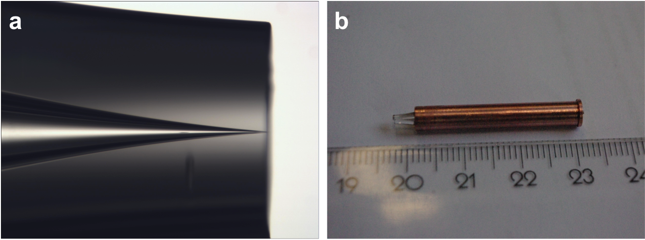
- Figure 2.(a) Side view Image
of a glass capillary. (b) A glass capillary epoxy glued into a cupper cylinder housing for cryogenic operation.
|
The behavior of cryogenic liquid jets upon expansion into vacuum strongly depends not only on the source parameters, but also on the
particular liquid material. Figure 3 shows some examples of micro-scopic liquid jets propagating in vacuum that we routinely produce at IKF. Figures
3a and 3b show liquid hydrogen and argon jets, respectively. Here, jet freezing that occurs shortly after the injection into vacuum leads to the
formation of a continuous, several millimeters long solid filament. The liquid-to-solid transition can be readily identified in our images as a
slight change in the jet optical features, as indicated by the arrows in Figs 3a and 3b. The rapid jet freezing is due to the very high volatility
of the hydrogen and argon liquids, which results in evaporation cooling rates exceeding 107 K s-1 for hydrogen
and 108 K s-1 for argon during early jet propagation times
(Grisenti et al., 2006,
Kühnel et al., 2011). The liquid nitrogen jet visible in Fig. 3c displays, on the other hand,
the Rayleigh breakup. The low liquid nitrogen vapor pressure at the triple point results in significantly lower evaporation cooling rates upon
vacuum expansion than for the liquid hydrogen and argon jets, thus producing more moderate quenches. The spontaneous breakup into a stream of
droplets indicates, in fact, that the jet remains liquid up to that point. Eventually, freezing of the droplets may start further downstream
from the breakup point. Whereas the observed rapid freezing of hydrogen and argon liquid jets represents the major obstacle that has to be
circumvented in order to produce RDBs of these liquids,
it offers, on the other side, novel opportunities to investigate structural
transformations in rapidly quenched liquids in order to significantly advance to advance our understanding of complex non-equilibrium
phase transition phenomena.
|
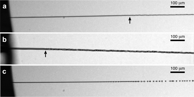
- Figure 3.(a) Liquid hydrogen
jet produced at a nominal source pressure of 12 bar and a source temperature of 15 K. (b) Liquid argon jet produced at 10 bar and 86 K. (c) Liquid nitrogen
jet produced at 8 bar and 70 K. The hydrogen and nitrogen beams are produced from a 5 μm diameter capillary orifice, whereas the argon jet issues from
a 8 μm diameter aperture. The arrows in (a) and (b) indicate approximately the location of the liquid-to-solid transition.
|